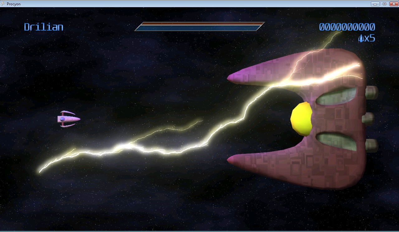
You’re flying your ship down a cavern, dodging and weaving through enemy fire. It’s becoming rapidly apparent, however, that you’re outmatched. So, desperate to survive, you flip The Switch. Yes, that switch. The one that you reserve for those…special occasions. Your ship charges up and releases bolt after deadly bolt of lightning into your opponents, devastating the entire enemy fleet.
At least, that’s the plan.
But how do you, the game developer, RENDER such an effect?
Lightning Is Fractally Right
As it turns out, generating lightning between two endpoints can be a deceptively simple thing to generate. It can be generated as an L-System (with some randomization per generation). Some simple pseudo-code follows: (note that this code, and really everything in this article, is geared towards generating 2D bolts; in general, that’s all you should need…in 3D, simply generate a bolt such that it’s offset relative to the camera’s view plane. Or you can do the offsets in the full three dimensions, it’s your choice)
segmentList.Add(new Segment(startPoint, endPoint));
offsetAmount = maximumOffset; // the maximum amount to offset a lightning vertex.
for each generation (some number of generations)
  for each segment that was in segmentList when this generation started
    segmentList.Remove(segment); // This segment is no longer necessary.

    midPoint = Average(startpoint, endPoint);
    // Offset the midpoint by a random amount along the normal.
    midPoint += Perpendicular(Normalize(endPoint-startPoint))*RandomFloat(-offsetAmount,offsetAmount);

    // Create two new segments that span from the start point to the end point,
    // but with the new (randomly-offset) midpoint.
    segmentList.Add(new Segment(startPoint, midPoint));
    segmentList.Add(new Segment(midPoint, endPoint));
  end for
  offsetAmount /= 2; // Each subsequent generation offsets at max half as much as the generation before.
end for
Essentially, on each generation, subdivide each line segment into two, and offset the new point a little bit. Each generation has half of the offset that the previous had.
So, for 5 generations, you would get:


That’s not bad. Already, it looks at least kinda like lightning. It has about the right shape. However, lightning frequently has branches: offshoots that go off in other directions.
To do this, occasionally when you split a bolt segment, instead of just adding two segments (one for each side of the split), you actually add three. The third segment just continues in roughly the first segment’s direction (with some randomization thrown in)
direction = midPoint - startPoint;
splitEnd = Rotate(direction, randomSmallAngle)*lengthScale + midPoint; // lengthScale is, for best results, < 1.  0.7 is a good value.
segmentList.Add(new Segment(midPoint, splitEnd));
Then, in subsequent generations, this, too, will get divided. It’s also a good idea to make these splits dimmer. Only the main lightning bolt should look fully-bright, as it’s the only one that actually connects to the target.
Using the same divisions as above (and using every other division), it looks like this:


Now that looks a little more like lightning! Well..at least the shape of it. But what about the rest?
Adding Some Glow
Initially, the system designed for Procyon used rounded beams. Each segment of the lightning bolt was rendered using three quads, each with a glow texture applied (to make it look like a rounded-off line). The rounded edges overlapped, creating joints. This looked pretty good:
..but as you can see, it tended to get quite bright. It only got brighter, too, as the bolt got smaller (and the overlaps got closer together). Trying to draw it dimmer presented additional problems: the overlaps became suddenly VERY noticeable, as little dots along the length of the bolt. Obviously, this just wouldn’t do. If you have the luxury of rendering the lightning to an offscreen buffer, you can render the bolts using max blending (D3DBLENDOP_MAX) to the offscreen buffer, then just blend that onto the main scene to avoid this problem. If you don’t have this luxury, you can create a vertex strip out of the lightning bolt by creating two vertices for each generated lighting point, and moving each of them along the 2D vertex normals (normals are perpendicular to the average of the directions two line segments that meet at the current vertex).
That is, you get something like this:
Animation
This is the fun part. How do you animate such a beast?
As with many things in computer graphics, it requires a lot of tweaking. What I found to be useful is as follows:
Each bolt is actually TWO bolts at a time. In this case every 1/3rd of a second, one of the bolts expires, but each bolt’s cycle is 1/6th of a second off. That is, at 60 frames per second:
- Frame 0: Bolt1 generated at full brightness
- Frame 10: Bolt1 is now at half brightness, Bolt2 is generated at full brightness
- Frame 20: A new Bolt1 is generated at full, Bolt2 is now at half brightness
- Frame 30: A new Bolt2 is generated at full, Bolt1 is now at half brightness
- Frame 40: A new Bolt1 is generated at full, Bolt2 is now at half brightness
- Etc…
Basically, they alternate. Of course, just having static bolts fading out doesn’t work very well, so every frame it can be useful to jitter each point just a tiny bit (it looks fairly cool to jitter the split endpoints even more than that, it makes the whole thing look more dynamic). This gives:
And, of course, you can move the endpoints around…say, if you happen to have your lightning targetting some moving enemies:
So that’s it! Lightning isn’t terribly difficult to render, and it can look super-cool when it’s all complete.
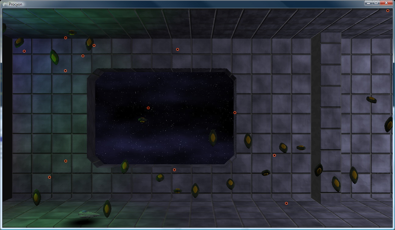
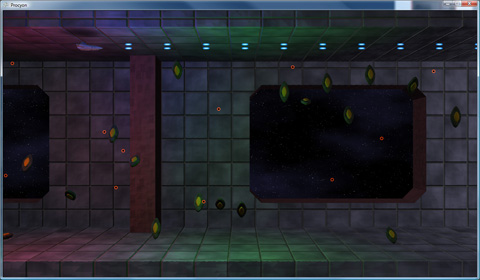
This previous weekend, I was able to accomplish another major milestone in game development: The Scrolling Background (TM) (C) (R) (BBQ).

Click to enlarge
The Skinny On Scrolling
The interesting thing about the scrolling method that I settled on is that it’s not based on any sort of overall world coordinate system. World coordinates don’t actually exist, the only true coordinate system is the screen coordinate system (with coordinates ranging from -16,-9 to +16,+9, for a delicious [and integer-tastic] 32:18 [2x 16:9] visible area).
So how does it work? Each level will be built out of tiles, in order. Each tile has the following data:
- A model to render
- Collision Data
- The Camera Path
The camera path for a tile is currently just an input position and an output position. That is, the position at which the camera ENTERS the tile, and the position at which the camera EXITS the tile.
Now, here’s the trick: Say you have two of the same tile next to each other. Each has an input coordinate of (0,1) and an output coordinate of (4, 0). What the system does is it moves the second one so that its input coordinate is in the same spot as the first one’s output coordinate. (that is, the second one’s input coordinate becomes effectively (4,0) like the first’s output coordinate and, relative to that, the second’s output coordinate becomes (8, -1)).
However, actual world coordinates aren’t strictly necessary, so whichever tile the camera is currently in is considered the “origin” tile. That is, it is used as the basis by which all other visible tiles get their on-screen positioning.
Thus, the setup is easy: figure out where on-screen (given the camera’s position in the tile) the tile should display, then make all of the visible tiles to the left and right relative to that.
This is nice for a few reasons:
First off, if, for some reason, a level were RIDICULOUSLY long, I would never have to worry about accumulating floating point round-off error.
The big thing is this allows me to have what is essentially a staple of the shoot-em-up game (and is actually quite visible in the video posted above): an endless loop of background.
These loops are especially useful for when fighting bosses. Say you’re zooming down a metallic corridor while scrapping with a boss that happens to be flying along with you. Rather than have to hope that the player finishes the fight before the camera hits the level’s end, you can just rely on the fact that the corridor will keep on looping until something triggers the loop’s end, signaling that the level should keep going (or end, assuming that there’s no more to the level).
This triggering system is not yet implemented, and I hope to get it done this weekend (though I have a ton of other, smaller items on the to-do list, so it may have to wait for the NEXT weekend).
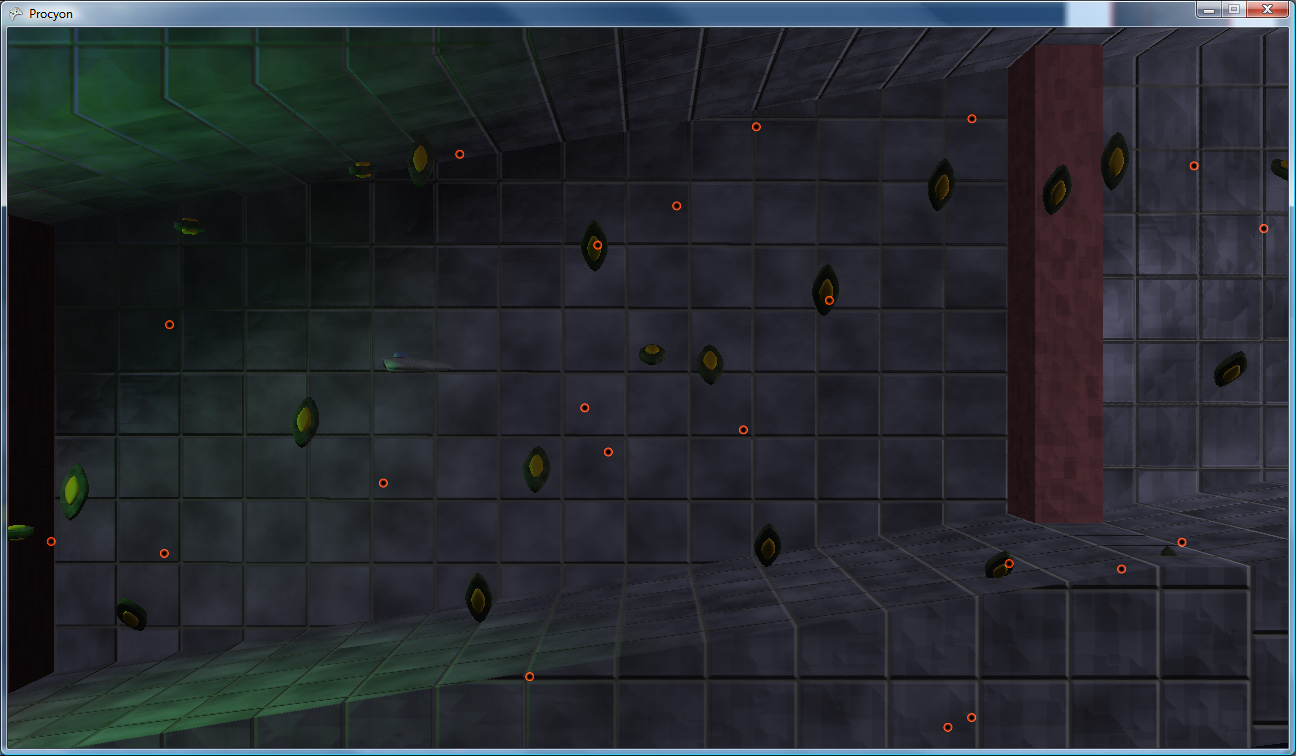
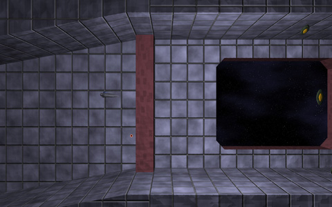
Proximity Alert
One design element that was tricky was signaling to the player that the ship is too close to a wall. The obvious metric is, of course, a shadow. However, standard shadows only cast in one direction, which would be great if all we cared about was distance to the floor. However, we really need “distance to any object.” This looks like a job for the existing lighting system!
A new type of “light” was designed: essentially a black light, which has a center, a length, and a radius (thus, the actual light is more like a line light than a point light). Consequently, the fakey shadow from the ship will “cast” onto any surrounding objects.

Click to enlarge
And, once again, that’s all we have time for on this week’s episode of “What Did Drilian Do Last Weekend”. Stay tuned next week, same Bat-Time, same Bat-Channel!
So I finally got something interesting working. While there’s no pretty shading or even eye candy, what there IS is an infinite plane renderer, using a grid. The idea was to use this for water rendering, but there’s an easier and less complicated way to do it (a la Far Cry) that I’m going to use instead. I just thought I’d finish this up anyway because it’s moderately novel (at least, to me. Maybe it’s not.)
A few pictures of it in action (Hooray for poorly-compressed JPGs and their many artifacts!):


Click to Enlarge
What makes this interesting (to me at least, if nobody else) is that the visible portions of the plane are (for the most part) the whole visible bit of the plane. Also, the grid spacing is interpolated in post-projection space, so it’s a constant-ish LOD across the screen (which was to be a great help in rendering water waves with the detail in the near waves, but not the far waves).
Here are some pictures of it with the gridlines:


Click to Enlarge
Advantages:
- With the exception of the four 4-component vectors used as shader constants, nothing is transferred to the card on a per-frame basis. The vertex/index buffers are completely static.
- A very minimum of the grid is off-screen. Thus, the transformations are reserved for the on-screen objects only
- With the screen-space linear interpolation of the grid, detail is concentrated where it’s needed.
Disadvantages:
- Complex. Finding the best four points for the on-screen representation of the grid wasn’t quite as easy as I had initially thought. Especially since there are 5 and 6 edge cases.
- The vertex shader is ever-so-slightly more complex than a normal shader. Just a few instructions, but every little bit, right?
- It actually is quite difficult to make it handle the variations in height necessary for a water wave renderer. Actually, I haven’t done that part yet (and since I’ve found an easier way of doing the same thing, I probably won’t). That is left as an exercise for the reader.
How does it work, you ask? Okay, nobody asked that, but I’m going to tell you anyway. Because that’s what I do.
First up is the on-CPU setup. Given a plane in the 4-vector form of [a, b, c, d] (i.e. ax + by + cz +d = 0)
- Project the plane into post-projection space. To transform a plane using the 4×4 transformation matrix T, you multiply the 4-vector plane representation by the matrix Transpose(Inverse(T)). I decided to do the plane clipping in post-projection space because the clipping against the frustum is easier there (as it’s a box instead of a sideways headless pyramid).
- Get the vertices of the intersection between the frustum and the plane.
- This intersection is the intersection of three planes: The two planes making up the frustum side, and the plane being rendered. However, since the planes of the frustum are axis-aligned planes in post-projection space, this can be simplified by substituting in the two known components (from the frustum planes) for that edge and solving for the third variable. For instance given the upper-left corner (x = -1, y = -1), z = -(a*x + b*y + d)/c.
- Once you have the third component, check to make sure that it is within the valid half-cube range (Note: in Direct3D, visible post-perspective space is within the half-cube where x is in [-1, 1], y is in [-1, 1] and z is in [0, 1]). If it IS in range, add it to the list of edge points.
- There can be at most six points generated by this set of checks (giving one polygonal edge per frustum plane. 6 edges = 6 points, see?)
- Ensure a clockwise winding order for the points. I used the gift-wrap sort of method, starting at the point nearest the screen, do a 2D check (ignore Z) to find the “most clockwise” point along the way (i.e. the point at which, given the line between the current point and the next point, all vertices are to the right of that line).
- This is the complicated part. We need to get the number of points to exactly 4 (as what the shader is expecting is a quad)
- Given 3 points, duplicate the one nearest the camera.
- Given 5 points:
- Find the diagonal edge that crosses from one side to an adjacent side (i.e crosses from the top side to the right side, as opposed to left to right)
- Look at the intersection between that diagonal line and the two sides that it currently doesn’t touch.
- Choose the side that has the intersection point nearest the screen, and extend the corresponding point along the diagonal to the intersection point
- At that point, along the edge where that intersection was, there are now three collinear points. Remove the one in the middle, which brings the total down to four points
- Given 6 points:
- There are two diagonals that cross from one side to an adjacent one, so we’ll pick the one that represents the far plane intersection (the z coordinate of both of the points on this diagonal will be 1).
- That diagonal gets extended to both of the sides that it doesn’t touch, similar to the 5-point case. Except that it extends both directions instead of just the one.
- Remove the two redundant vertices
- Send the 4 points to GPU (I pass them in in the world matrix slot, since they’re 4 float4 values).
Okay, that was the worst of it. Now there’s the GPU-side bits:
- The mesh input is a grid of u,v coordinates ranging from 0 to 1. Linearly interpolate between the four post-projective planar intersection points passed in from the CPU using the u,v values. worldSpace = lerp(lerp(inMatrix[0], inMatrix[1], in.u), lerp(inMatrix[3], inMatrix[2], in.u), in.v) The 3 and 2 are in that order because the vertices are given in clockwise order.
- Using the inverse viewproj matrix, project these points back into worldspace.
- The worldspace x and z can be used as texture coordinates (scaled, if you want. I use them verbatim right now).
- Reproject the worldspace coordinates back into projected space. This is necessary because the linearly interpolated points are not perspective-correct (causing the texture mapping to totally flip out. It was like a bad flashback to the original Playstation. I do not wish that upon others).
Math-heavy? Yep.
Poorly explained in this post? Probably.
Able to be cleared up by questions in the comments section? You betcha.
Hope this has been informative (though it’s more of a dry read than I would have liked).